Commodore 1541C repair
I bought a Commodore 1541C drive a while ago. It was sold as a faulty unit. The seller said it was broken, and that it makes chattering noises. The chattering noise is normal at power-up because the head is pulled back by the stepper motor and hits the end-stop, but he did also say that it didn't read disks. I have cleaned the heads, and it does read disks, however the motor never stop!
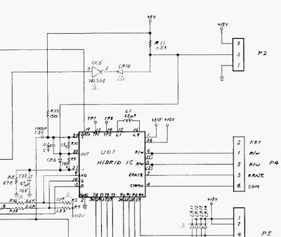
The fault I have now is that the motor spins continuously. I measured motor control signals at the gate-array after the CIA IC, and motor control signal looks ok there. The signal is high at power-on and then goes low (stop) after the start-up sequence as expected. In the schematic below the motor signal from the gate-array comes in on one of the inputs of the inverter UC6. The CR10 is shorted by traces on the PCB, because UC6 is 74LS06 and not a 04 as it says in the schematics. This is because 06 has open-collector outputs, and therefore doesn't need a diode to isolate it from whatever comes next in the circuit. I don't know why they did this. Maybe a question of availability?
The motor signal is inverted by UC6 and should be pulled up to +5V via the R11 resistor to stop the motor after the start-up sequence ends, but the signal goes from 0V to 0.66V. That sounds suspiciously like a diode or a pn-junction somewhere turning on and preventing the signal from going high. The UC6 was swapped out so no fault there.
What about the diode CR6 next to the Hybrid IC. That looks suspicious doesn't it ? 0.66V ? What if C22 has shorted ? Well then ground is also at CR6's cathod, and it will hold 0.7V over it pulled by R11.
So I desoldered CR6 and the motor stops as it should. Then I know the fault is perhaps on the net somewhere below CR6 in the schematic.
What about the Hybrid IC ? Well that is a difficult question. The Hybrid IC holds all the analog electronics that amplifies the data comming from the magnetic platter. The IC is also a part of a phase locked loop that adjust the motor speed (see the + and - pins) to keep the same speed for all disks with different drag. Because this is in a loop then there could be something in the loop telling the motor to go all the time, or maybe something has shorted inside the Hybrid IC. Lets just hope it is C22. I desoldered C22 and its pins are shorted.
I put in a new electrolytic cap at C22, and I resoldered CR6. The drive operates correctly now. Thats one happy owner of a working classic Commodore Disk Station ! :) The drive needs a recapping.
I made a video of it also.
I also bought a faulty cassette player that I fixed. That was more a mechanical than electronics repair.
Full schematics:
http://personalpages.tds.net/~rcarlsen/cbm/1541/1541C/


Kommentarer
Legg inn en kommentar