Programming an ATTiny85 for low power fridge alarm
This project is about a fridge alarm powered by solar cells, and energy stored in super capasitors. It is mostly about programming the ATtiny85 MCU in Assembly. I wanted to learn more about the AVR core. That is why I programmed using assembly language. The program is very short, and the features of C is not needed.
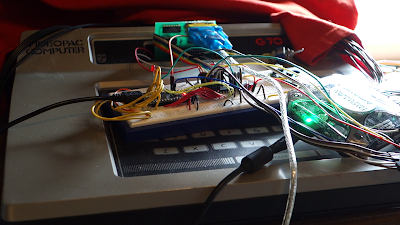
The circuit has an AEM SUCA R2 as power supply, an ATTiny85, one IR diode, one photodiode, a 2n7000 NMOS driving a magnetic transducer.
Unfortunately in this testing I don't have a microamps meter. I've been monitoring the voltage decent of two parallel capacitors of total 3000uF.

Why AVRA
AVRA is an assembler for Atmel AVR microcontrollers. It is simple and effective. It's open source. There are examples here at 043-045 that gets you going. Also lately I've been using Linux more and more, and installing AVRA was just a single command line.
The program

The flow diagram shown above is the whole program. The program checks the sensors every 8 seconds and if the fridge door is not closed properly the sensor will return high, where it checks again after two seconds to see if it is still high, then it starts the buzzer and repeats until the door is shut.
Power
There is not much power to go by with indoor lighting. The attiny was chosen because of its <1 microamps sleep modes. Most of the time the MCU is in power down mode. Also, to get to <1 microamps, the ADC must be shut down in power down mode.
Other measures. I took to keep the power down. I removed all wait loops except the one that pulses the buzzer. I was initially running the ATtiny at 1 MHz. Buzzing for say 0.25s is still a huge amount of cycles for the cpu. I set the clock to 16kHz (128kHz watchdog clock with clkdiv8). Now a delay between the pulses is only about 20 instructions compared to hundreds. I also reduced the number of waves to the buzzer to about 15. It is more like a tick sound. The sound is still loud, and uses a lot less energy.
I tried to get the buzzer going in sleep. timer0 has a "CTC mode, toggle pin on compare match", but the pin stops toggling when the cpu is sleeping. I also tried the idle mode, which only turns off the clock for the cpu and flash, didn't work.
Source Code
All of this information can be found in the datasheet. You should keep it close to you. The first thing you need to do in the source code is to set up the reset and interrupt vectors. These are located at the beginning of the program memory. We use the .org directive to tell the assembler to start from 0000. We place a jump instruction to the setup label, which is the beginning of our code.
While playing with the avr_sim simulator, I learned that the stack pointer also must be initialized. We initialize it to the end of the SRAM.
The stack is used for storing the return address. It can also be used for pushing data, like working registers. In my program I'm not pushing anything on the stack, only the rcall instructions and interrupts themselves do that. In C you would not have to think about this but here yo must be aware that your working registers can be overwritten at any moment. That is why I have used r16 in the main code, and r17 inside the watchdog interrupt service routine (ISR). You would normally also want to push the status register to the stack when entering an ISR. If there is branching instructions right after the ISR is finished, the status registers might be changed by the ISR resulting in incorrect branching. Now, the interrupt I'm using here is a wake-up from sleep, which will always be right after the sleep instruction. We put a nop after the sleep instruction to be sure.
The sleep routines were difficult wake up from using the watchdog timer. There is a special dance that needs to be taken when changing the watchdog registers. I think the datasheet was explaining this in a clumpsy way. What was really needed was to first write a Watchdog_OFF routine, and always execute that first before changing its registers.
; Fridge alarm, attiny85
.nolist
.include "tn85def.inc"
.list
.equ SENS_PWR = PB0
.equ SENS_IN = PB3
.equ BUZZER = PB4
.equ LED_PIN = PB2
.def tmp = r16
.def tmpisr = r17
.def loopCt = r18 ; delay loop count
.def iLoopRl = r24 ; inner loop register low
.def iLoopRh = r25 ; inner loop register high
.org 0x0000 ; reset vector
rjmp setup
.org WDTaddr ; Watchdog time-out vector
rjmp WDT_isr
;.cseg
.org 0x000f
setup:
ldi tmp, low(RAMEND) ; init stack pointer
out SPL, tmp
ldi tmp, high(RAMEND)
out SPH, tmp
sbi DDRB, SENS_PWR ; SENSOR power output
sbi DDRB, BUZZER ; BUZZER output
sbi DDRB, LED_PIN
clr tmp
out PORTB, tmp
out ADCSRA, tmp
ldi tmp, 0x0f
out PRR, tmp
rcall alarm_sound
main:
rcall checksensor
brbs SREG_C, first_detected_wait
not_detected:
rcall sleep_8s
rjmp main
first_detected_wait:
rcall sleep_2s
detect_again:
rcall checksensor
brbs SREG_C, alarm_sound
rjmp not_detected
alarm_sound:
ldi loopCt, 15
alarm_oloop:
sbi PORTB, BUZZER
;nop
cbi PORTB, BUZZER
dec loopCt
brne alarm_oloop
nop
rcall sleep_2s
rjmp detect_again
; subroutines
; -----------------------------------------------------------------------------
sleep_2s:
rcall WDT_off
; setup watchdog for interrupt and not reset, and 8s timeout
ldi tmp, (1<<WDIE)|(1<<WDE)
out WDTCR, tmp
ldi tmp, (0<<WDP3)|(1<<WDIE)|(1<<WDP2)|(1<<WDP1)|(0<<WDP0)
out WDTCR, tmp
ldi tmp, 0x0f
out PRR, tmp
ldi tmp, (1<<SE)|(1<<SM1)|(0<<SM1)
out MCUCR, tmp
sleep
ret
sleep_8s:
rcall WDT_off
; setup watchdog for interrupt and not reset, and 8s timeout
ldi tmp, (1<<WDIE)|(1<<WDE)
out WDTCR, tmp
ldi tmp, (1<<WDP3)|(1<<WDIE)|(0<<WDP2)|(0<<WDP1)|(1<<WDP0)
out WDTCR, tmp
ldi tmp, 0x0f
out PRR, tmp
ldi tmp, (1<<SE)|(1<<SM1)|(0<<SM1)
out MCUCR, tmp
sleep
ret
checksensor:
; sets carry bit if light detected
sbi PORTB,SENS_PWR
ldi loopCt, 6
checksensor_loop:
dec loopCt
brne checksensor_loop
clc
sbic PINB,SENS_IN
sec
cbi PORTB,SENS_PWR
ret
WDT_off:
cli
wdr
; Clear WDRF in MCUSR
ldi tmp, (0<<WDRF)
out MCUSR, tmp
; Write logical one to WDCE and WDE
; Keep old prescaler setting to prevent unintentional Watchdog Reset
in tmp, WDTCR
ori tmp, (1<<WDCE)|(1<<WDE)
out WDTCR, tmp
; Turn off WDT
ldi tmp, (0<<WDE)
out WDTCR, tmp
sei
ret
; Interrupt service routines
; -----------------------------------------------------------------------------
; watchdog
WDT_isr:
rcall WDT_off
ldi tmpisr, 0
out MCUSR, tmpisr
reti
Makefile
# assemble with AVR Assembler (AVRA)
MCU=attiny85
# run FOSC at 1 MHz
#FUSE_L=0x62
# run FOSC at 16 kHz
FUSE_L=0x44
FUSE_H=0xDF
FUSE_E=0xFF
F_CPU=1200000
AS=avra
AVRDUDE=avrdude
TARGET=main
ASFLAGS=-I ../avra/include
SRCS = main.asm
all:
${AS} ${ASFLAGS} -o ${TARGET} ${SRCS}
flash:
${AVRDUDE} -p ${MCU} -c usbasp -B250 -U flash:w:${TARGET}.hex:i -F -P usb
fuse:
$(AVRDUDE) -p ${MCU} -c usbasp -B250 -U hfuse:w:${FUSE_H}:m -U lfuse:w:${FUSE_L}:m efuse:w:${FUSE_L}:m
clean:
rm -f *.asm~ *.hex *.obj *.cof
Links
http://avra.sourceforge.net/https://blog.podkalicki.com/how-to-install-avr-assembler-avra-on-linux-ubuntu/

Kommentarer
Legg inn en kommentar