Innlegg

Viser innlegg fra 2015

The Beam and Ball Project - Part 2 Servo Control

Bilde
  Software (continued) Servo Control To control the servo the microcontroller need to produce this 50 Hz waveform shown below. The resolution is defined by the microcontroller because the servo is an analog device. There are mainly three ways of doing it. Delays Set output, then do delay. This is a bad way of doing it. The program is halted for every delay. However if you want to mash up some code to test your servo, this is the way to go. Consumes the whole CPU Good and quick technique to test servos. Hardware PWM The most positive about hardware PWM is that the overhead is 0. The CPU usage is practically zero, and only one or two instruction cycles are used to set a new pulsewidth. Running the PWM at 50Hz demands that the PIC16F887 is ran in max 1 MHz due to max prescaler settings. So at the beginning of the project I went with 1 MHz. The 10bit capable Hardware PWM uses a CCPx module, and TMR2. TMR2 is 8 bit, however the remaining two least significant b

The Beam and Ball Project - Part 1 Setup and distance measurement

Bilde
This is a write-up for my YouTube series: Introduction The hardware and designing a function for the distance measurement. So I've always wanted to learn PID Control. It's a closed loop control system used to move and regulate something into a given target. PID control is fairly simple to implement, however the math behind can be intimidating for anyone. I remember back in College that I was put off by all the focus on differential equations. However PID control was a great subject to learn diff-equations, don't get me wrong. The main concept of PID got lost for me a long the way back then. To get me started again what isn' better than doing a fun project that involves this form of control. Here is a link to my Beam and Ball Project series on YouTube. https://youtu.be/R5ryRxh4_7c?list=PLtQOf_JULmrQr-Htio6THf0MxvWWyOdG_ The Hardware  A good way for me to get started was to digg out my trusty EasyPIC5 development board from MikroElektronika from 2008. It has

Commodore 1541C repair

Bilde
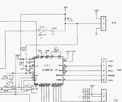
I bought a Commodore 1541C drive a while ago. It was sold as a faulty unit. The seller said it was broken, and that it makes chattering noises. The chattering noise is normal at power-up because the head is pulled back by the stepper motor and hits the end-stop, but he did also say that it didn't read disks. I have cleaned the heads, and it does read disks, however the motor never stop! The fault I have now is that the motor spins continuously. I measured motor control signals at the gate-array after the CIA IC, and motor control signal looks ok there. The signal is high at power-on and then goes low (stop) after the start-up sequence as expected. In the schematic below the motor signal from the gate-array comes in on one of the inputs of the inverter UC6. The CR10 is shorted by traces on the PCB, because UC6 is 74LS06 and not a 04 as it says in the schematics. This is because 06 has open-collector outputs, and therefore doesn't need a diode to isolate it from whatever comes

C64 "Searching for $" Serial Buss issue repaired

Bilde
After playing with a C64 i picked up recently and the disk drive that came with it, I notcied that loading failed once in a while.. It was not the disk or the drive, because by trying the drive on my other C64 the drive works. I read online that on the Serial Bus there are buffers with open collector output (7604) and they fail often. I replaced one and, Voilá !

C64 SID trouble

Bilde
SID chips fail all the time and especially the filters fail often. One SID chip is not equal to another. Been experiensing various weirdness with the audio from the C64. Audio seems very sharp but some games sid tunes sounds as if a channel is missing. However the case is not that simple. Listen to the track at about 9 minutes in. Nice and crisp synth sound however the bass lead is missing.. You can hear the same tune but with propper filtered bass lead recordded from a good SID chip here at 6:28: My video above also has a track of Jeroen Tel Robocop. To me it sounds fine. Great Giana sisters is missing some parts of the audio and the wind noise in the very beginning of the game is gone. In the image below I've used a BASIC program called SIDBench , and all channels and waveforms seem fine except when filters are switched on. Below you can see three recordings of audio from running SIDbench on several chips.. Recordings are lined up in Audacity and view mode is Spect

Commodore 64 29y later + composite mod

Bilde
Welcome to my first blog post. This blog will cover my repair and mod adventure of old computers. Mostly the C64. Computer architecture will be discussed later where I look at a simple cpu starting with the accumulator. We will build it with descrete components and make so slow that we can see and feel where information is moving.. This is my first videoe where I brought my trusty old Commodore 64 out of the cupboard, and inspect it for capacitor leaks and corrosion. The RF moduler has been ruined once in the 80s, but no need for that in 2015. The RF output is repurpose as a composite output with a simple modification. The modulator gets a wire from Composite signal to the RF RCA connector. The RF signal was cut from the board.  The pcb and traces in the middle of the pic shows some signs of corrotion, but I'm not sure. However there is exposed traces there. Couldn't find corrotion here, but these caps might need replacing soon. In