The Beam and Ball Project - Part 1 Setup and distance measurement
This is a write-up for my YouTube series:
So I've always wanted to learn PID Control. It's a closed loop control system used to move and regulate something into a given target. PID control is fairly simple to implement, however the math behind can be intimidating for anyone. I remember back in College that I was put off by all the focus on differential equations. However PID control was a great subject to learn diff-equations, don't get me wrong. The main concept of PID got lost for me a long the way back then. To get me started again what isn' better than doing a fun project that involves this form of control.
Here is a link to my Beam and Ball Project series on YouTube.
https://youtu.be/R5ryRxh4_7c?list=PLtQOf_JULmrQr-Htio6THf0MxvWWyOdG_
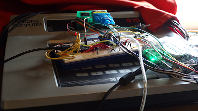
A good way for me to get started was to digg out my trusty EasyPIC5 development board from MikroElektronika from 2008. It has a 40pin dip PIC16F887, LCD screen, lots of buttons and leds.

The board is designed to get your projects up and running fast. You can also see the icstation ultrasonic transducer to the left, and the el-cheepo micro servo from Tower Pro.
I mounted everything with cardbox and hotglue, and used gardening wire to connect the servo arm to the beam. To get a pivoting point I used an old broken Zalman fan. A half part of a pringles serves as the beam. All glued in place.

After glueing the beam in place, the servo had to be coupled to the beam using semi hard wire.

 The ultrasonic tranducer from icstation.

As you can see, the servo has been replaced with a higher quality one because the tiny servo broke too easily. Now after hooking up the hardware and adding the ball with an owl inside, we can concentrate on the firmware bit.
Power to the ultrasonic transducer is taken from the dev. board. The power to servo is too much for the dev. board and is taken from an external 5V source.

This CCP module in capture mode can detect an event of rising and falling edges, or every fourth edge or 16th edge. At very moment of an event, the module copies the 16bit wide TIMER1, which is free running, into another register. In this way we don't have to worry how long it will take for our code to read the TMR1H/L value and how much error our latency will bring us, the value has been safely captured into the CCPRxH/L registers. We need to store them in memory though because the CCPRxH/L is of course overwritten in the next event.
In this project I used it to only trigger on single falling or rising edges. So at the very first thing we need to do is to configure the module for rising edge. Then by sending a 15us pulse on the trig pin we immediately wait for the CCPxIF flag to go high. When that flag is high we are certain that our TIMER1 has been captured and copied into CCPRxH/L without any latency.
Now while the blip from the transmitter is flying through the air at a speed of about 343 m/s, we have time to let our program store the captured value from CCPRxH/L into RAM, say variable a, reset the interrupt flag, reconfigure to trigger on falling edge and let the cpu wait for the next event. Meanwhile the wave bounce off the ball and returns to the receiver and the transducer let the echo pin go low. Once again the CCP module captures the TIMER1 value into CCPRxH/K. Our code stores this value again into ram, say variable b.
Finally we return b - a = time which we can recompute into an absolute distance, but for my project I've let it remain as a dimensionless value. I simply use it as is.
Some design questions comes to mind. How fast can the timer run before it wraps around 2^16 when our beam is about 24 cm long ? At a certain level above sea level the speed of sound is about 343 m/s.
(Values in paranthesis are values when Fosc=8Mhz.)
The longest distance between transducer and object is:
(The distance between the ball and transducer is 2cm - 24cm.)
Hans.
Introduction
The hardware and designing a function for the distance measurement.
So I've always wanted to learn PID Control. It's a closed loop control system used to move and regulate something into a given target. PID control is fairly simple to implement, however the math behind can be intimidating for anyone. I remember back in College that I was put off by all the focus on differential equations. However PID control was a great subject to learn diff-equations, don't get me wrong. The main concept of PID got lost for me a long the way back then. To get me started again what isn' better than doing a fun project that involves this form of control.
Here is a link to my Beam and Ball Project series on YouTube.
https://youtu.be/R5ryRxh4_7c?list=PLtQOf_JULmrQr-Htio6THf0MxvWWyOdG_
The Hardware
A good way for me to get started was to digg out my trusty EasyPIC5 development board from MikroElektronika from 2008. It has a 40pin dip PIC16F887, LCD screen, lots of buttons and leds.

The board is designed to get your projects up and running fast. You can also see the icstation ultrasonic transducer to the left, and the el-cheepo micro servo from Tower Pro.
I mounted everything with cardbox and hotglue, and used gardening wire to connect the servo arm to the beam. To get a pivoting point I used an old broken Zalman fan. A half part of a pringles serves as the beam. All glued in place.

After glueing the beam in place, the servo had to be coupled to the beam using semi hard wire.


As you can see, the servo has been replaced with a higher quality one because the tiny servo broke too easily. Now after hooking up the hardware and adding the ball with an owl inside, we can concentrate on the firmware bit.
Power to the ultrasonic transducer is taken from the dev. board. The power to servo is too much for the dev. board and is taken from an external 5V source.
Software
Designing a program for the Transducer and servo functionsDistance measurement function
For distance measurements we use the icstation.com ultrasonic transducer. It works by triggering a 15us pulse. After a while it's echo pin will go high, then it will go low when an echo arrives. It's up to us to decode that pulsewidth into a distance measure. There are several ways to do this. You can do it by polling, or even better you can use the PIC's CCP module in capture mode.

This CCP module in capture mode can detect an event of rising and falling edges, or every fourth edge or 16th edge. At very moment of an event, the module copies the 16bit wide TIMER1, which is free running, into another register. In this way we don't have to worry how long it will take for our code to read the TMR1H/L value and how much error our latency will bring us, the value has been safely captured into the CCPRxH/L registers. We need to store them in memory though because the CCPRxH/L is of course overwritten in the next event.
In this project I used it to only trigger on single falling or rising edges. So at the very first thing we need to do is to configure the module for rising edge. Then by sending a 15us pulse on the trig pin we immediately wait for the CCPxIF flag to go high. When that flag is high we are certain that our TIMER1 has been captured and copied into CCPRxH/L without any latency.
Now while the blip from the transmitter is flying through the air at a speed of about 343 m/s, we have time to let our program store the captured value from CCPRxH/L into RAM, say variable a, reset the interrupt flag, reconfigure to trigger on falling edge and let the cpu wait for the next event. Meanwhile the wave bounce off the ball and returns to the receiver and the transducer let the echo pin go low. Once again the CCP module captures the TIMER1 value into CCPRxH/K. Our code stores this value again into ram, say variable b.
Finally we return b - a = time which we can recompute into an absolute distance, but for my project I've let it remain as a dimensionless value. I simply use it as is.
Some design questions comes to mind. How fast can the timer run before it wraps around 2^16 when our beam is about 24 cm long ? At a certain level above sea level the speed of sound is about 343 m/s.
(Values in paranthesis are values when Fosc=8Mhz.)
- v_sound ~ 343 m/s
- Fosc=1MHz (8MHz later !)
- Fsystem= Fosc/4 = 250 kHz (2MHz)
- TIMER1-tick: t_tick = 1 / Fosc/4 * prescaler = 4 us (0.5 us)
- t_period = 2^16 ticks * 4 us/tick = 262.144 ms (32.768 ms)
The longest distance between transducer and object is:
- distance_max = t_period * v_sound / 2 = ~45 m (5.6m)
(The distance between the ball and transducer is 2cm - 24cm.)
- resolution [mm/tick]= v_sound * timer1_tick = 343 m/s * 4 us = 1.372 mm/tick (0.1715 mm/tick)
- # of ticks when distance is 2cm: 20mm * 2 / 1.372mm/tick ~15 ticks (233 ticks)
- # of ticks when distance is 24cm: 240 mm * 2 / 1.372 mm/tick ~ 350 ticks (2799 ticks)
Hans.

Kommentarer
Legg inn en kommentar