The Videopac G7000 composite mod

Introduction
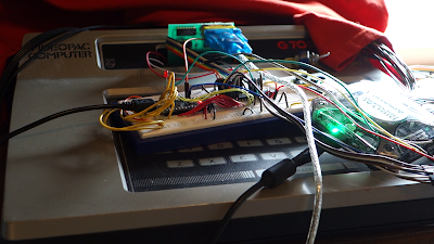
This is a write-up of my experience with a custom composite mod board for the Videopac G7000 game console, and the mod installation. The write-up is based on my youtube video below (the second one). In this blog post we will demonstrate the installation and picture quality.
The sites gamesx and coolretroprojects linked below have installation instructions and schematics. Coolretroprojects sell a board, and they have a nice installation manual in PDF format.
Links:
http://gamesx.com/wiki/doku.php?id=av%3Ag7000_av#picture_of_g7000_internals
http://www.coolretroprojects.com/Mods-Kits.html
Videos:
Video: Building a circuit for a friend of mine.
Video: Installing the composite mod.
This is the video you are reading a write-up of right now.
Background
The Videopac G7000 also known as Odyssey 2, however different internally and different composite mod board for it. The G7000 was introduced to the market in 1978. It has a RF modulator only.. The mainboard has the composite signal, however the signal is too weak and small on its own to drive the video input of a TV set. The signal needs roughly 2x amplification, 75 ohm output impedance and a sane DC-level. This is where the composite mod board comes in. It's a non-inverting amplifier built up by three transistors.
Other things i noticed while probing the motherboard with a scope; when the RF box is attached, the composite signal is very small, and the DC level seems to be dragged up over 5V by the RF box.. Using the RF box and modulator box at the same time is not adviceable.
Comments to the two installation instructions
I soldered up the circuit shown at the Gamesx site (linked above). The installation instructions there tell you to attach wires to points under the metal shielding convering the video circuits. Removing the shield is no easy task. The installation guide (PDF) on coolretroprojects is easy to follow. They re-use the modulator cable, and attach all those wires to the composite mod board. From there, wires go to the output connectors.
I did not like that the manual tells you to to install the board inside the top case and the connectors in the bottom case. This method would make the top and bottom case inseparable. Why not attach the mod board on the same case as the output connectors ? I'll demonstrate below (or see the second video above).
I did not like that the manual tells you to to install the board inside the top case and the connectors in the bottom case. This method would make the top and bottom case inseparable. Why not attach the mod board on the same case as the output connectors ? I'll demonstrate below (or see the second video above).
The mod board

Soldering the mod board to the modulator cable

Figure: Wires ordered in a sequential fashion.
Modulator cable desoldered.
The final installation
I'll let the images speak for themselves. Thanks for watching my videos or reading my blog.


Kommentarer
Legg inn en kommentar